Software-defined radio (SDR) is a technology that replaces traditional hardware-based radio components with software.
This post is not meant to be an encyclopedia in the SDR universe but a landing page with links and references to the most important resources for getting started in the field.
I use the official kit “RTL-SDR Blog V4 RTL2832 1PPM TCXO HF BiasT SMA Software Defined Radio + Antennas” [Link]. Follow along with the vendor’s “Quick Install Guide” [Link].
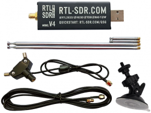
Datasheet source [Link].
| Tuner Chip | R828D |
| ADC Chip | RTL2832U 8-bits |
| Frequency Range | 500 kHz to 1.766 GHz |
| Bandwidth | 2.56 MHz stable (up to 3.2 MHz with drops) |
| Typical Input Impedance | 50 Ohms |
| Typical Current Draw | 250 – 270 mA |
| HF Implementation | Upconverter with 28.8 MHz LO |
| Input Connector | 1x SMA |
| USB Connector | USB-A Male |
| Local Oscillator Stability | 1PPM TCXO |
| Bias Tee | 4.5V, 180mA (software switchable) |
| Enclosure | Aluminum |
| Heat Dissipation | Thermal Pad to Aluminum Enclosure |
| Front-End RF Design | Triplexor with switchable notch |
| Transmit Capability | None |
SPECTRUM FOR THIS HARDWARE
| MF 500~526.5 kHz | Maritime / Marine Band Distress and emergency (Morse Code), navigation |
| MF 540~1700 kHz | AM Broadcasting Band 10 kHz steps (+/- 5 kHz) Channels: 540, 550, 560… 1700 |
| HF 3~30 MHz | Shortwave AM Broadcasting Radio |
| HF 13.56 MHz | ISM (Industrial, Scientific, and Medical) Band |
| HF 27 MHz | CB (Citizens Band) class D: 10 kHz wide (AM or SSB mode) Unlicensed, 40 channels: 26.965, 26.975… 27.185 |
| HF 40.68 MHz | ISM (Industrial, Scientific, and Medical) Band |
| VHF 50~54 MHz | 6M HAM Band [Link] |
| VHF 54~88 MHz | Digital TV – Channels 2-6 |
| VHF 88~108 MHz | FM Broadcast Band: 200 kHz steps (+/- 100 kHz) Channels: 88.1 MHz, 88.3 MHz… 107.9 MHz |
| VHF 108~137 MHz | Aviation Band (aka “airband”) AM (legacy compatibility) or SSB mode (best) 108 to 117.95 MHz: 200 channels 50 kHz steps 118 to 136.975 MHz: 760 channels 25 kHz steps |
| VHF 144~148 MHz | 2M HAM Band [Link] ARISS-SSTV from at 145.8 MHz NFM [Link] [Link] |
| VHF 156~174 MHz | Marine Band (aka “Maritime”) 28 channels with 50 kHz step Or 88 channels with 25 kHz steps |
| VHF 161~161.45 MHz | Railways in the US and Canada |
| VHF 162.4~162.55 MHz | NOAA Weather Radio (weather, alerts, and emergency) 8 channels 25 kHz step under Narrow FM modulation. Channels: 162.400 MHz, 162.425 MHz… 162.550 MHz Alerts preceded by 1050 Hz attention tone for 10 sec [Link] |
| VHF 174~216 MHz | Digital TV – Channels 7-13 |
| VHF 222~225 MHz | 1.35M HAM Band [Link] |
| UHF 433 MHz | ISM (Industrial, Scientific, and Medical) Band Centered at 433.92 MHz and channels with 25 kHz step. |
| UHF 470~512 MHz UHF 614~890 MHz |
Digital TV Channels 14-20 and 38-83 respectively. Channel 37 (608~614 MHz) is reserved for radio astronomy. |
| UHF 915 MHz | ISM (Industrial, Scientific, and Medical) Band Modulation according to application: CSS, FSK, QAM… Usage: LoRa, ZigBee, RFID, Sensors, Remotes… |
| UHF 1227.60 MHz UHF 1575.42 MHz |
GNSS (Global Navigation Satellite System) [Link] GPS L2 and L1 frequencies respectively (BPSK modulation). Also used by Galileo (EU), GLONASS (RU), and BeiDou (CN). |
| UHF 1660~1670 MHz | GOES Weather Satellite [Link] Transmission of high-resolution meteorological images. |
| UHF 1698~1707 MHz | NOAA Weather Satellite [Link] Transmission of high-resolution meteorological images. |
ANTENNAS AND FILTERS
The RTL-SDR kit can easily tune into FM stations out of the box but is unlikely to receive decent-quality AM stations. The reason is that the spectrum is crowded with all types of noise and interference.
There are two Dipole (half-wave long) Antennas included in the kit:
- Telescopic 46-198 cm
- Ranges from 75 MHz to 325 MHz.
- Most of the VHF Band:
- FM Broadcast
- Aviation
- Marine
- NOAA Weather Radio
- Military Aviation
- Telescopic 14-30 cm.
- Ranges from 500 MHz to 1 GHz.
- Partial UHF Band:
- TV Channels.
- Radio astronomy.
- Mobile broadband service.
- ISM (e.g. 433/915 MHz remote controllers/RFIDs).
- Industrial (e.g. SCADA).
- Pagers.
- Aeronautical radionavigation.
The quality of the antenna defines the quality of the whole circuit and consecutively, its reception.
The best way is to do it right from the start and choose an antenna that precisely matches the signal that will be received. Eventually, crafting antennas is not a bad idea.
As an example, see the block diagram of a dual-conversion heterodyne receiver:

- Antenna
- Source of the raw incoming RF signals that need to be sized according to the desired frequency.
- BPF₁
- A Band-Pass Filter that selects a specific frequency band. E.g. AM Band, FM Band.
- LNA
- Amplifies weak signals while introducing minimal noise, ensuring the signal strength is sufficient for further processing.
- BPF₂
- Removes unwanted image frequencies to prevent interference during mixing.
- First Mixer
- The signal is mixed with a local oscillator signal to produce an intermediate frequency (IF₁).
- BPF₃
- A Band-Pass Filter that filters the first IF signal to select the desired channel (e.g. Radio Station), reducing interference from adjacent signals.
- Second Mixer
- The filtered IF₁ signal is mixed with a second local oscillator signal, converting it to a lower second IF (IF₂) or baseband.
- BPF₄
- A Band-Pass Filter that filters the final IF₂ signal, ensuring that only the desired channel passes through for cleaner output.
- Output
- The result of the whole circuit is ready to be demodulated so the data or audio can be extracted.
WAVELENGTH CALCULATION FROM FREQUENCY
Hz
Full Wavelength: – m
1/2 Wavelength: – m
1/4 Wavelength: – m
A half wavelength is a rule of thumb for the length of a simple antenna to achieve optimal transmission.
FREQUENCY CALCULATION FROM ANTENNA LENGTH
m
Frequency: – Hz
Frequency if 1/2 wavelength: – Hz
Frequency if 1/4 wavelength: – Hz
MOST POPULAR ANTENNA TYPES
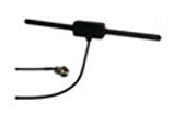
A monopole antenna is a half-dipole vertical metal structure or rod. The most common monopole is a quarter of a wave tall, the minimum size for it to self-resonate.

Whip antenna is used on mobile and portable radios in the VHF and UHF bands such as FM radio.

A normal-mode helix (aka “Rubber ducky”) is the most common antenna used on portable two-way radios due to its small size.
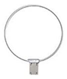
Full-wave loop antennas have the highest radiation resistance, and hence the highest efficiency of all antennas.
AM VS FM
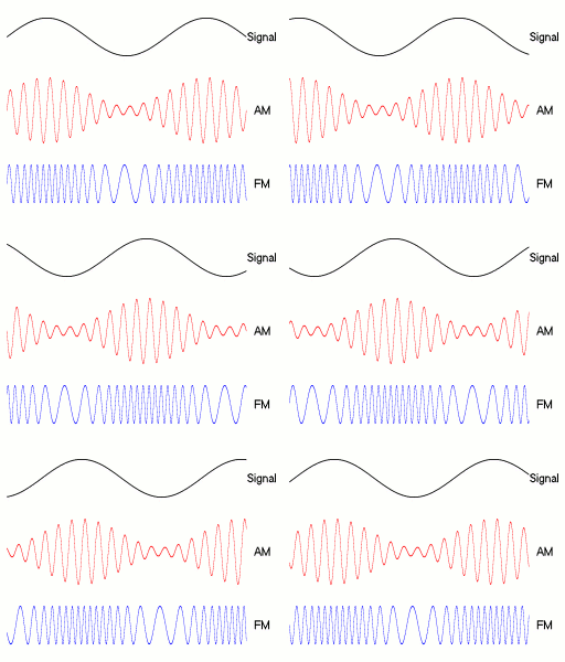
As illustrated above, in AM, the amplitude of the carrier signal is modulated by the waveform of the transmitted signal. In FM, the carrier frequency shifts back and forth around its central frequency.
This means an AM radio station uses a very narrow spectrum band, allowing many stations to be placed close together with minimal spacing. In contrast, FM requires a wider bandwidth around the center frequency. Essentially, up to 20 AM channels can fit within the bandwidth of a single FM channel.
Another important factor is frequency. AM stations transmit at lower frequencies, allowing their signals to travel farther than FM. However, this comes at the expense of audio quality. AM is more suitable for voice, while FM is ideal for music.
A loop (aka “donut”) antenna is a particularly popular antenna for tuning AM stations. It has a variable capacitor in the center that adjusts the fine-tuning to the desired frequency, filtering every thing else.
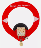
This is called Magnetic Coupling: when a circuit’s inductance and capacitance resonate, it maximizes energy transfer and selectively amplifies the desired frequency while rejecting others.
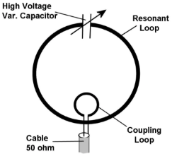
This type of antenna is very compact (excellent for low frequencies) and highly directional (minimally susceptible to interference or noise).
| CD | 10 to 20,000 Hz |
| FM | 20 to 15,000 Hz |
| AM | 50 to 7,000 Hz |
| Telephone | 200 to 3,400 Hz |
AM (Amplitude Modulation)
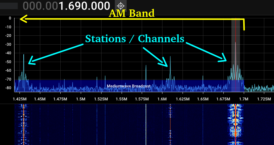
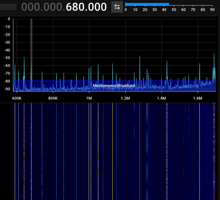
Since the AM modulation happens to be in amplitude, the bandwidth is narrow and can be identified as peaks in the FFT (Fast Fourier Transformation).
FM (Frequency Modulation)
Normal Bandwidth
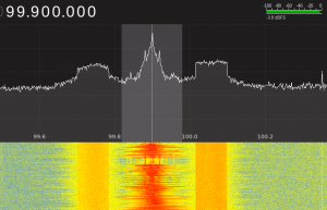
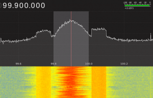
Wide Bandwidth
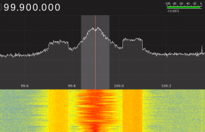
Narrow Bandwidth
Multiple stations.
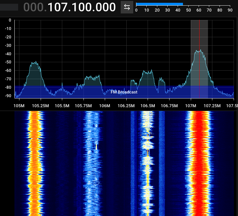
A 57 kHz subcarrier (phase-locked to the third harmonic of the stereo pilot tone) is used to carry a low-bandwidth digital Radio Data System (RDS) signal. Since it is only capable of transporting 1,187.5 bits per second, it is only suitable for text.
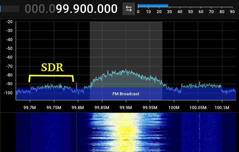
See more information about the type of information that RDS can carry at [Link].
VHF AIRBAND
Use a dipole antenna positioned vertically, and expand them to 60 cm each. Since dipole antennas are naturally half-wave antennas, each rod is equivalent to 1/4 of the wavelength.
This setup will match the ~125 MHz of the VHF band where the aviation communication happens.
It is easy to tune with AM or SSB, bandwidth of 5 kHz, and squelch will be your best friend to reduce the noise of the static when there is no transmission going on.
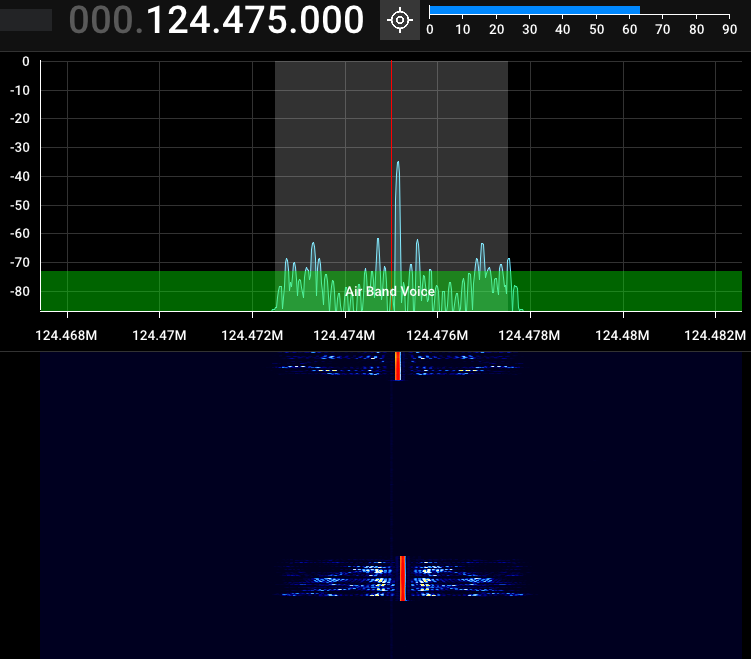
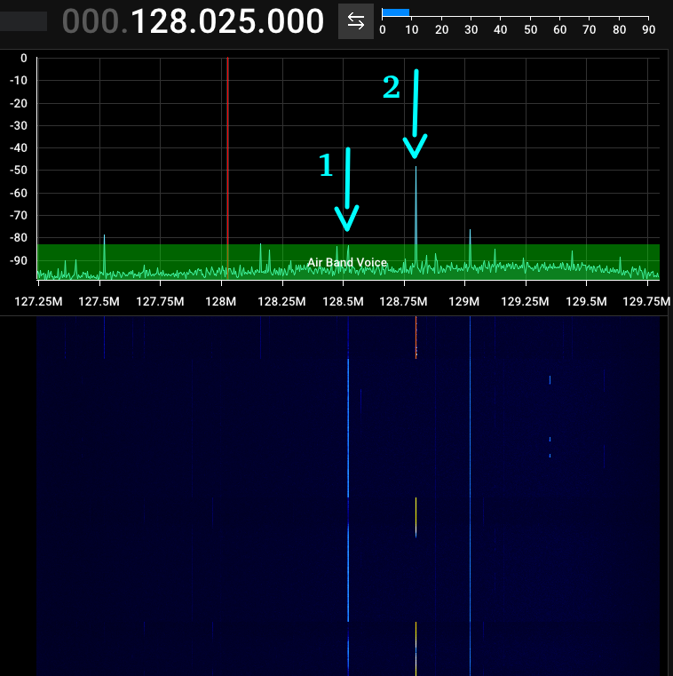
In another moment, I identified an aircraft transmitting what appeared to be silence in one carrier (#1), then alternating to another carrier (#2) when transmitting voice.
Transmissions are intermittent. Be patient and watch the waterfall for evidence of activity.
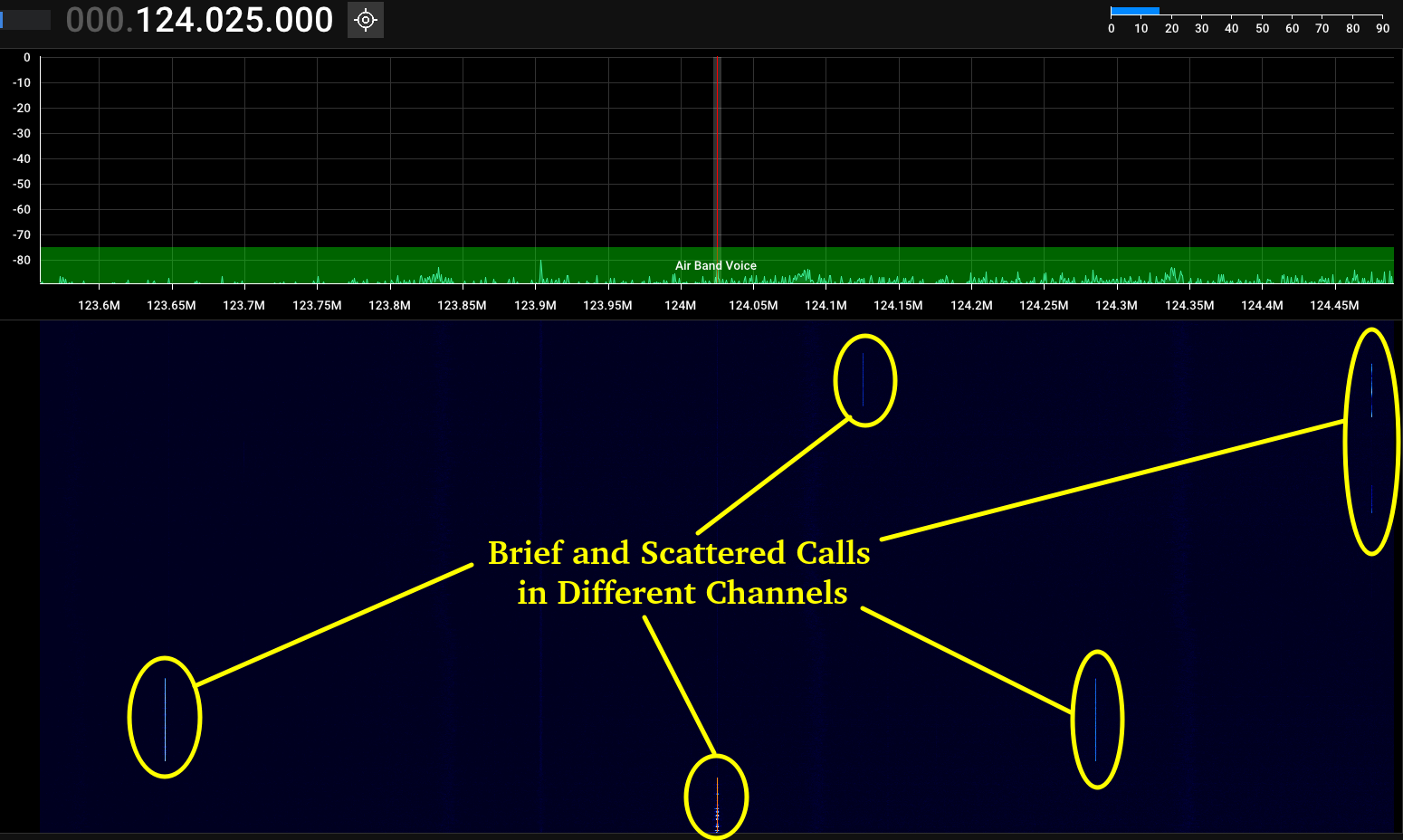
Some sources might even transmit simultaneously in multiple channels.
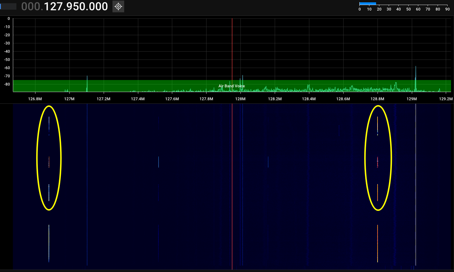
If you’re within an airport’s range, check for its Automatic Terminal Information Service (ATIS) frequency. ATIS is a 24/7 automated system that provides airport information to pilots. It helps confirm if you’re within range to communicate with the airport tower. If not, you may still hear one-way communication from approaching aircraft.
MARINE BAND
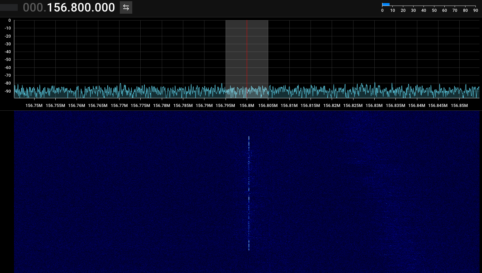
Used for voice communication from ship-to-ship and ship-to-shore with limited transmitter power to 25 watts, giving them a range of about 100 kilometers.
The telescopic antennas in the dipole should be 45 cm each. Target 156.8 MHz, set modulation to FM, and be patient because it might take a long while to see any activity.
| CH | Ship Transmit (MHz) |
Ship Receive (MHz) |
Use |
|---|---|---|---|
| 1 | 156.050 | 160.650 | Public Correspondence, Port Operation |
| 2 | 156.100 | 160.700 | Public Correspondence, Port Operation |
| 3 | 156.150 | 160.750 | Public Correspondence, Port Operation |
| 4 | 156.200 | 160.800 | Public Correspondence, Port Operation |
| 5 | 156.250 | 160.850 | Public Correspondence, Port Operation |
| 16 | 156.800 | Distress, Safety, and Calling.
Ships required to carry radio, USCG, & most coast |
|
| 18 | 156.900 | 161.500 | Port Operation |
| 19 | 156.950 | 161.550 | Port Operation |
| 21 | 156.950 | 161.550 | Port Operation |
| 22 | 156.950 | 161.550 | Port Operation |
| 23 | 157.150 | 161.750 | Port Operation |
| 60 | 156.025 | 160.625 | Public Correspondence, Port Operation |
| 61 | 156.075 | 160.675 | Public Correspondence, Port Operation |
| 62 | 156.125 | 160.725 | Public Correspondence, Port Operation |
| 63 | 156.175 | 160.775 | Public Correspondence, Port Operation |
| 64 | 156.225 | 160.825 | Public Correspondence, Port Operation |
| 65 | 156.275 | 160.875 | Public Correspondence, Port Operation |
| 66 | 156.325 | 160.925 | Public Correspondence, Port Operation |
| 78 | 156.925 | 161.525 | Port Operation |
| 79 | 156.975 | 161.575 | Port Operation |
| 80 | 157.025 | 161.625 | Port Operation |
| 81 | 157.075 | 161.675 | Port Operation |
| 82 | 157.125 | 161.725 | Public Correspondence, Port Operation |
| 83 | 157.175 | 161.775 | Public Correspondence |
| 83 | 157.425 | 162.025 | Public Correspondence |
Check out the Full List of Channels [Link].
WEATHER RADIO
Not much different than tuning on a regular FM broadcast station but with a narrowband (NFM).
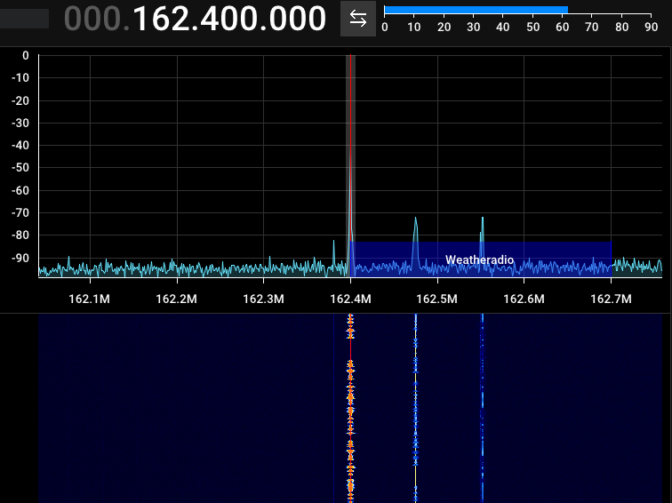
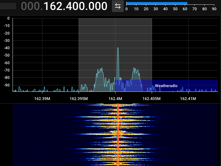
It appears to retransmit the same information in multiple frequencies.
TYPES OF MODULATION
FSK
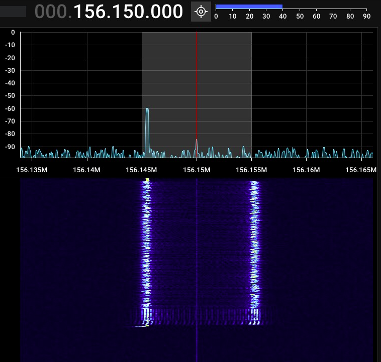
This appears to be a regular 2-FSK that I captured the spectrum and waterfall images but could not decode.
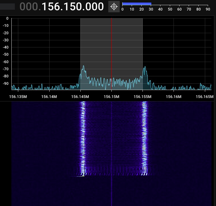
The transmission is likely digital data. The lower frequency represents 0 and the higher represents 1, or vice-versa. It looks like it signals the end of transmission at a lower frequency.
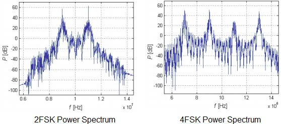
In comparison, a 4-FSK has four distinct peaks in the FFT. Each represents a digital value (0, 1, 2, or 3).
SATELLITE TRACKING
There are many apps and websites with real-time position and other telemetry data.
See the ISS (International Space Station) position from N2YO.com [Link].
Gpredict is a fantastic free and open-source software [Link].
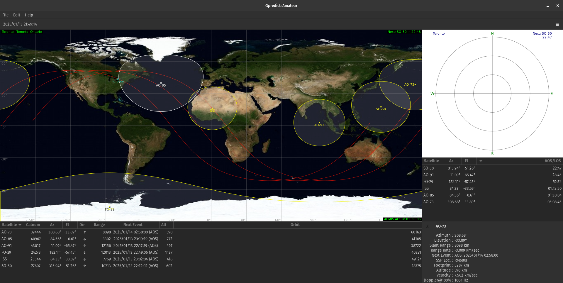
The website SatDump [Link] contains a list of the most relevant satellites and details about frequency, instrument status, modulations, and more. See also OrbitalFocus [Link].
RECEIVING SATELLITE SIGNAL
Many satellites transmit (continuously or scheduled) in open channels and can be decoded/demodulated by anyone.
What you need to know:
- x
The V-dipole antenna with a 120°, aka DP-120, works well for NOAA SSTV reception.
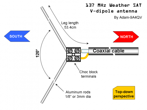
You can see the official paper [Link] and blog posting [Link] from Adam-9A4QV about making this antenna.
MAIN APPS AND DRIVERS
- Linux
- SDR++ [Link]
- A cross-platform and open-source SDR software.
-
wget https://github.com/AlexandreRouma/SDRPlusPlus/releases/download/nightly/sdrpp_ubuntu_jammy_amd64.deb
sudo dpkg -i sdrpp_ubuntu_jammy_amd64.deb
- GQRX [Link]
- An open-source SDR receiver.
-
sudo apt install gqrx-sdr -y
- GNU Radio [Link]
- Signal processing runtime and signal processing software development toolkit.
-
sudo apt install gnuradio -y
- Gpredict [Link]
- Satellite Tracker.
-
sudo apt install gpredict -y
- SatDump [Link]
- It is an incredible receiver software with a huge list of satellites and profiles already set for acquiring and processing the signals.
-
sudo apt install git build-essential cmake g++ pkgconf libfftw3-dev libpng-dev libtiff-dev libjemalloc-dev libcurl4-openssl-dev libvolk-dev libnng-dev libglfw3-dev zenity portaudio19-dev libzstd-dev libhdf5-dev librtlsdr-dev libhackrf-dev libairspy-dev libairspyhf-dev libad9361-dev libiio-dev libbladerf-dev libomp-dev ocl-icd-opencl-dev intel-opencl-icd mesa-opencl-icd -y
sudo dpkg -i satdump_1.2.2_ubuntu_24.04_amd64.deb
- NOAA APT Decoder [Link]
- As the name implies, it decodes data from VAW files.
-
sudo apt install noaa-apt_1.4.1-1_amd64.deb -y
- QSSTV [Link]
- Decode SSTV images from ISS (International Space Station).
-
sudo apt install qsstv -y
- SSTV Decoder [Link] and PySSTV [Link]
- Decode SSTV from .WAV file.
-
git clone https://github.com/colaclanth/sstv.git && cd sstv
sstv -d audio_file.wav -o decoded_image.png
-
pip3 install pysstv
python3 -m pysstv audio_file.wav decoded_image.png
- SDR++ [Link]
- Android
It is worth mentioning because of its relevance but unfortunately, the following apps do not run on Linux.
- Zadig (driver download tool)
- SDR Sharp
- SDRuno
- Airspy C#
DRIVER INSTALLATION ON LINUX
From source code:
sudo apt update && sudo apt upgrade -y
sudo apt purge ^librtlsdr -y
sudo rm -rvf /usr/lib/librtlsdr* /usr/include/rtl-sdr* /usr/local/lib/librtlsdr* /usr/local/include/rtl-sdr* /usr/local/include/rtl_* /usr/local/bin/rtl_*
sudo apt install libusb-1.0-0-dev git cmake pkg-config -y
git clone https://github.com/rtlsdrblog/rtl-sdr-blog
cd rtl-sdr-blog && mkdir build && cd build
cmake ../ -DINSTALL_UDEV_RULES=ON && make
sudo make install
sudo cp ../rtl-sdr.rules /etc/udev/rules.d/
sudo ldconfig
echo 'blacklist dvb_usb_rtl28xxu' | sudo tee --append /etc/modprobe.d/blacklist-dvb_usb_rtl28xxu.conf
From Package Manager:
sudo apt update && sudo apt upgrade -y
sudo apt install libusb-1.0-0-dev git cmake debhelper -y
git clone https://github.com/rtlsdrblog/rtl-sdr-blog
cd rtl-sdr-blog
sudo dpkg-buildpackage -b --no-sign
cd ..
sudo dpkg -i librtlsdr0_*.deb
sudo dpkg -i librtlsdr-dev_*.deb
sudo dpkg -i rtl-sdr_*.deb
LINUX APPLICATIONS