INDEX
- AM vs FM
- AM
- FM
- VHF Airband
- Marine Band
- Weather Radio
- Satellite Tracking
- Satellite Reception
AM VS FM
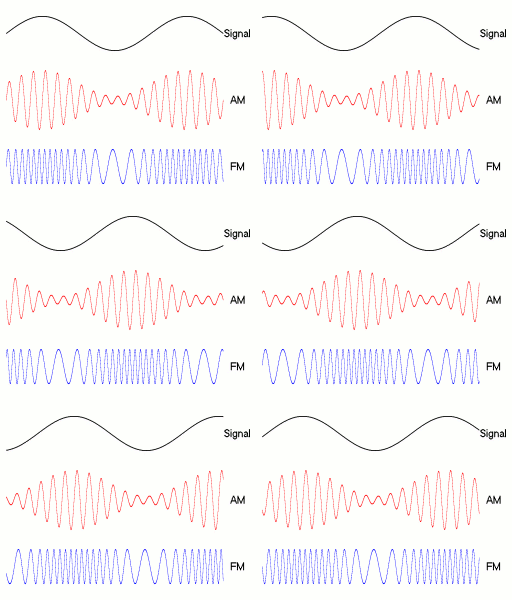
As illustrated above, AM modulates the amplitude of the carrier signal to match the transmitted waveform. FM shifts the carrier frequency back and forth around its center frequency.
This means an AM station occupies a very narrow spectrum band, allowing many stations to be placed close together. FM requires wider bandwidth around the center frequency. In practice, up to 20 AM channels can fit within the bandwidth of a single FM channel.
Frequency also plays an important role. AM stations transmit at lower frequencies, allowing their signals to travel farther than FM, though at the cost of audio quality. AM is better suited for voice, while FM is ideal for music.
A loop antenna (also called a “donut” antenna) is a popular choice for AM reception. It has a variable capacitor at the center that fine-tunes to the desired frequency and filters out everything else.
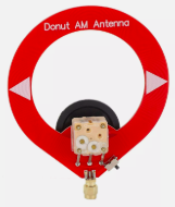
This works through magnetic coupling: when a circuit’s inductance and capacitance resonate together, energy transfer is maximized and the desired frequency is amplified while others are rejected.
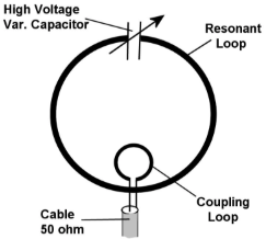
This type of antenna is very compact (well suited for low frequencies) and highly directional (resistant to interference and noise).
| CD | 10 to 20,000 Hz |
| FM | 20 to 15,000 Hz |
| AM | 50 to 7,000 Hz |
| Telephone | 200 to 3,400 Hz |
AM (Amplitude Modulation)
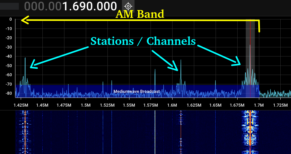
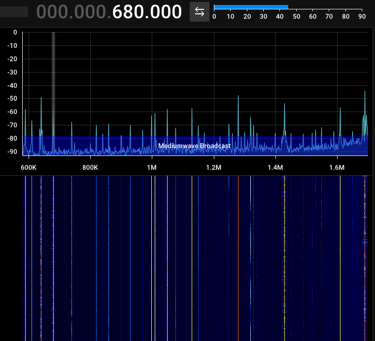
Because AM modulation occurs in amplitude, the bandwidth is narrow and AM stations appear as distinct peaks in the FFT (Fast Fourier Transform).
FM (Frequency Modulation)
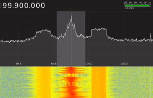
Normal Bandwidth
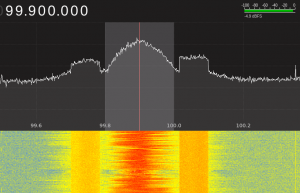
Wide Bandwidth
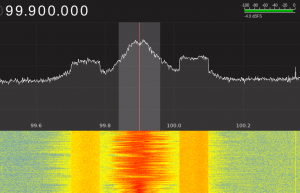
Narrow Bandwidth
Multiple stations.
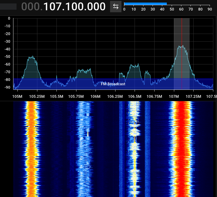
A 57 kHz subcarrier (phase-locked to the third harmonic of the stereo pilot tone) carries a low-bandwidth Radio Data System (RDS) signal. At only 1,187.5 bits per second, it is only suitable for text.
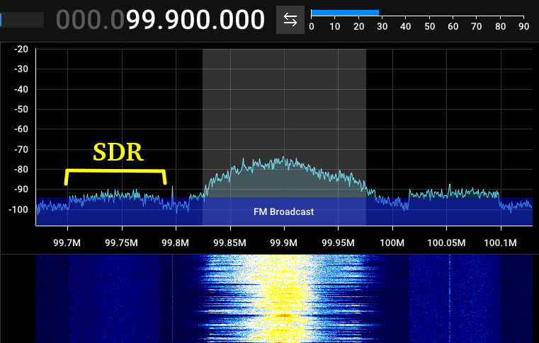
See more information about what RDS can carry at [Link].
VHF AIRBAND
Use a vertically positioned dipole antenna with each rod extended to 60 cm. Since dipole antennas are half-wave antennas, each rod represents 1/4 of the wavelength. This matches the ~125 MHz range used for aviation communication.
Tune with AM or SSB at a bandwidth of 5 kHz. Use squelch to cut the static noise between transmissions.
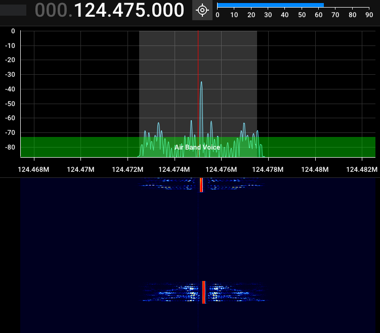
In one instance, I observed an aircraft transmitting silence on one carrier (#1), then switching to a second carrier (#2) when transmitting voice.
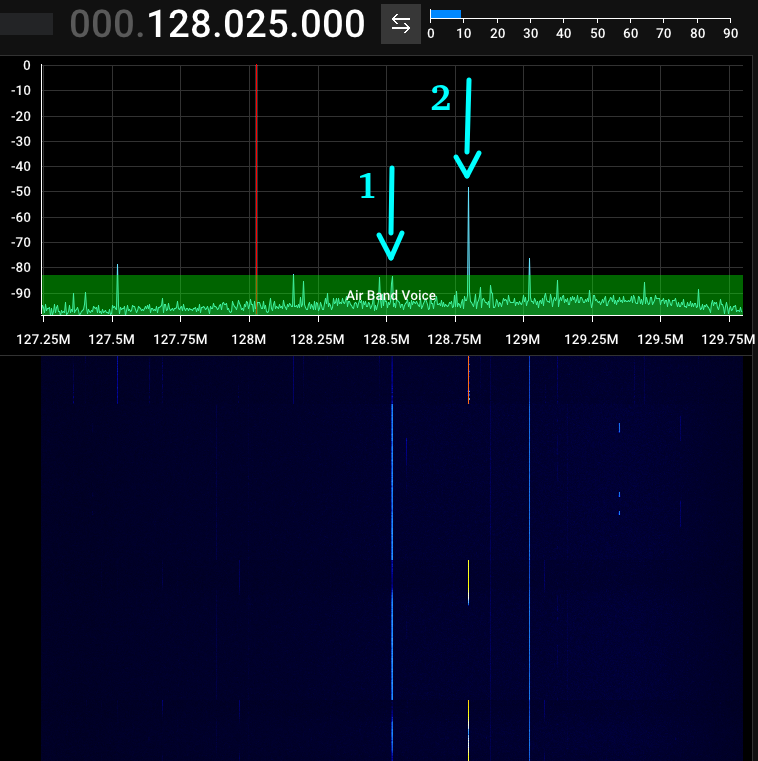
Transmissions are intermittent. Be patient and watch the waterfall for signs of activity.
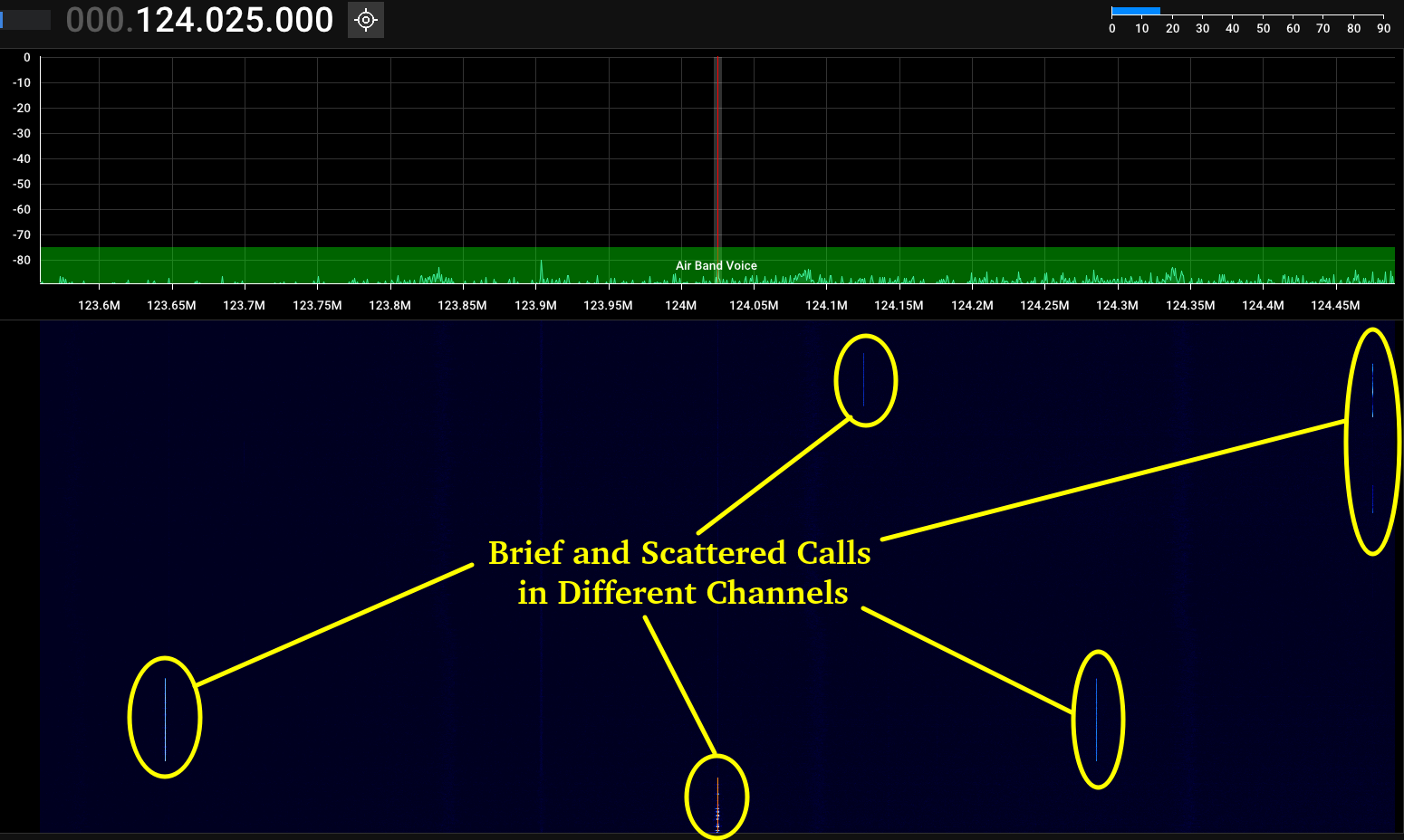
Some sources may transmit on multiple channels simultaneously.
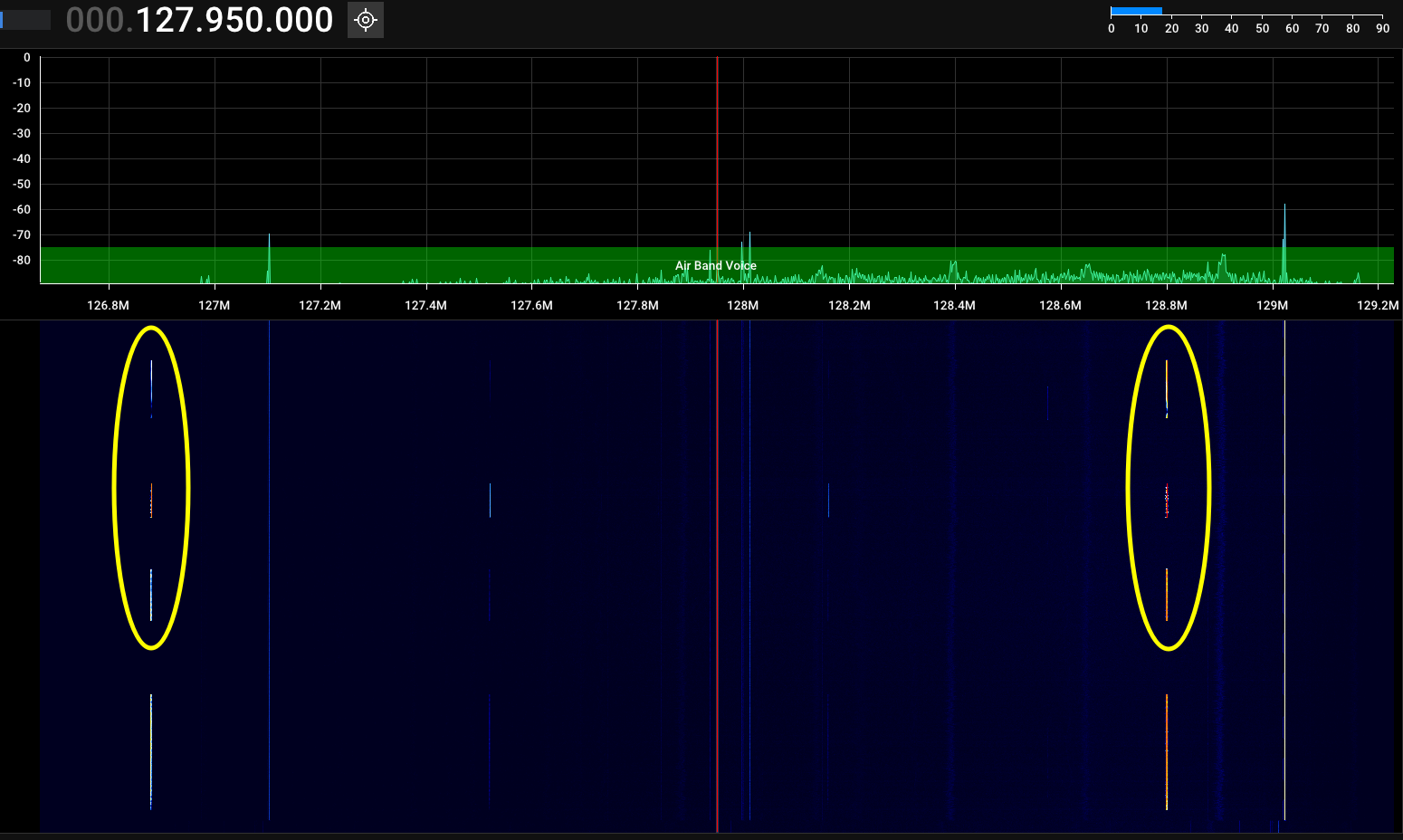
If you are within range of an airport, look up its Automatic Terminal Information Service (ATIS) frequency. ATIS is a 24/7 automated broadcast providing airport information to pilots. It is a good way to confirm you are within range of the tower. If not, you may still pick up one-way transmissions from approaching aircraft.
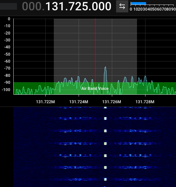
You may also notice short, high-pitched transmissions on the airband. These are ACARS (Aircraft Communications Addressing and Reporting System), a digital system aircraft use to send and receive short telemetry messages.
Standard ACARS uses a global frequency of 131.550 MHz. Some countries use additional frequencies; Canada also uses 131.475 and 131.725 MHz. Decoding ACARS is straightforward.
Here is a sample audio file with several ACARS occurrences [Link].
MARINE BAND
Used for ship-to-ship and ship-to-shore voice communication. Transmitter power is limited to 25 watts, giving a range of about 100 kilometers.
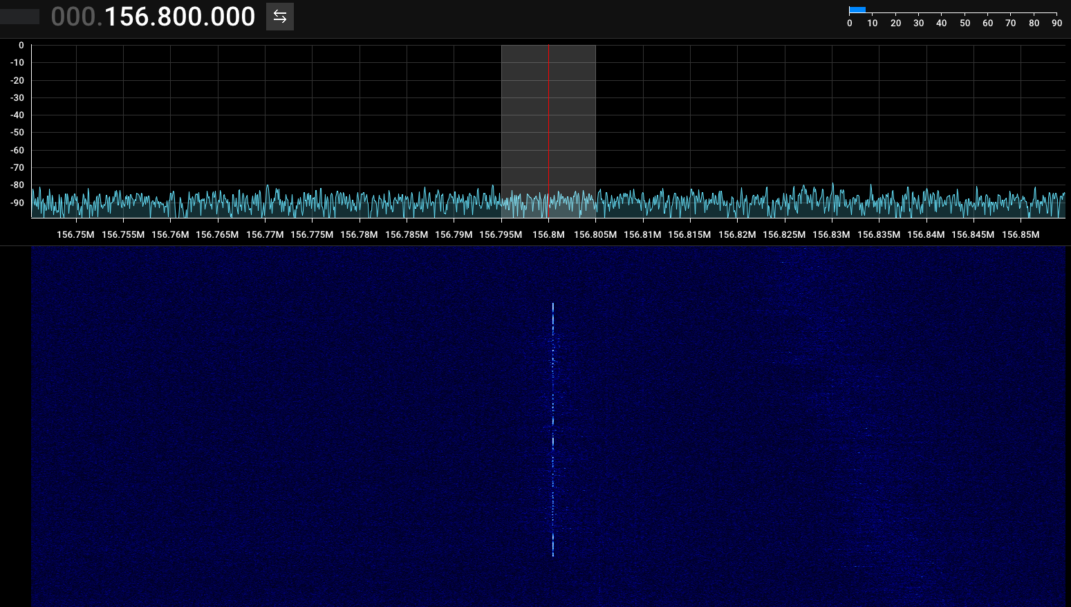
Set each telescopic antenna rod to 45 cm. Target 156.8 MHz, set modulation to FM, and be patient as activity may be infrequent.
| CH | Ship Transmit (MHz) |
Ship Receive (MHz) |
Use |
|---|---|---|---|
| 1 | 156.050 | 160.650 | Public Correspondence, Port Operation |
| 2 | 156.100 | 160.700 | Public Correspondence, Port Operation |
| 3 | 156.150 | 160.750 | Public Correspondence, Port Operation |
| 4 | 156.200 | 160.800 | Public Correspondence, Port Operation |
| 5 | 156.250 | 160.850 | Public Correspondence, Port Operation |
| 16 | 156.800 | Distress, Safety, and Calling.
Ships required to carry radio, USCG, & most coast |
|
| 18 | 156.900 | 161.500 | Port Operation |
| 19 | 156.950 | 161.550 | Port Operation |
| 21 | 156.950 | 161.550 | Port Operation |
| 22 | 156.950 | 161.550 | Port Operation |
| 23 | 157.150 | 161.750 | Port Operation |
| 60 | 156.025 | 160.625 | Public Correspondence, Port Operation |
| 61 | 156.075 | 160.675 | Public Correspondence, Port Operation |
| 62 | 156.125 | 160.725 | Public Correspondence, Port Operation |
| 63 | 156.175 | 160.775 | Public Correspondence, Port Operation |
| 64 | 156.225 | 160.825 | Public Correspondence, Port Operation |
| 65 | 156.275 | 160.875 | Public Correspondence, Port Operation |
| 66 | 156.325 | 160.925 | Public Correspondence, Port Operation |
| 78 | 156.925 | 161.525 | Port Operation |
| 79 | 156.975 | 161.575 | Port Operation |
| 80 | 157.025 | 161.625 | Port Operation |
| 81 | 157.075 | 161.675 | Port Operation |
| 82 | 157.125 | 161.725 | Public Correspondence, Port Operation |
| 83 | 157.175 | 161.775 | Public Correspondence |
| 83 | 157.425 | 162.025 | Public Correspondence |
Check out the Full List of Channels [Link].
WEATHER RADIO
Tuning weather radio is similar to a regular FM broadcast station, but uses narrowband FM (NFM).
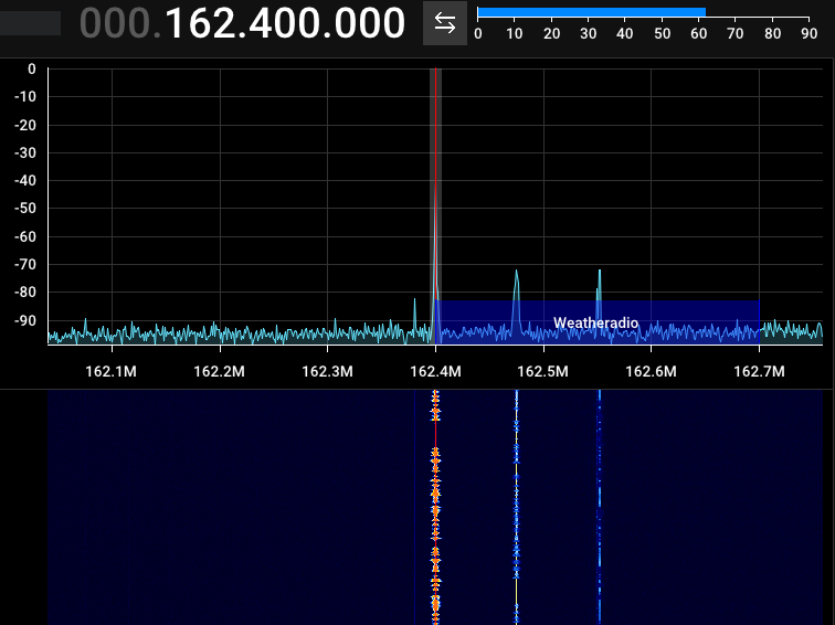
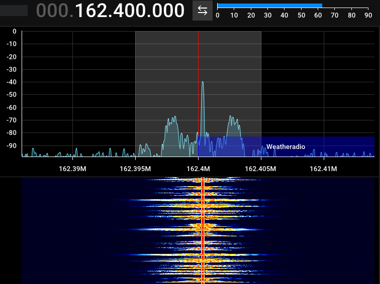
The same information appears to be rebroadcast across multiple frequencies.
TYPES OF MODULATION
FSK
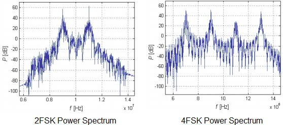
This appears to be a standard 2-FSK signal. I captured the spectrum and waterfall images but was unable to decode it.
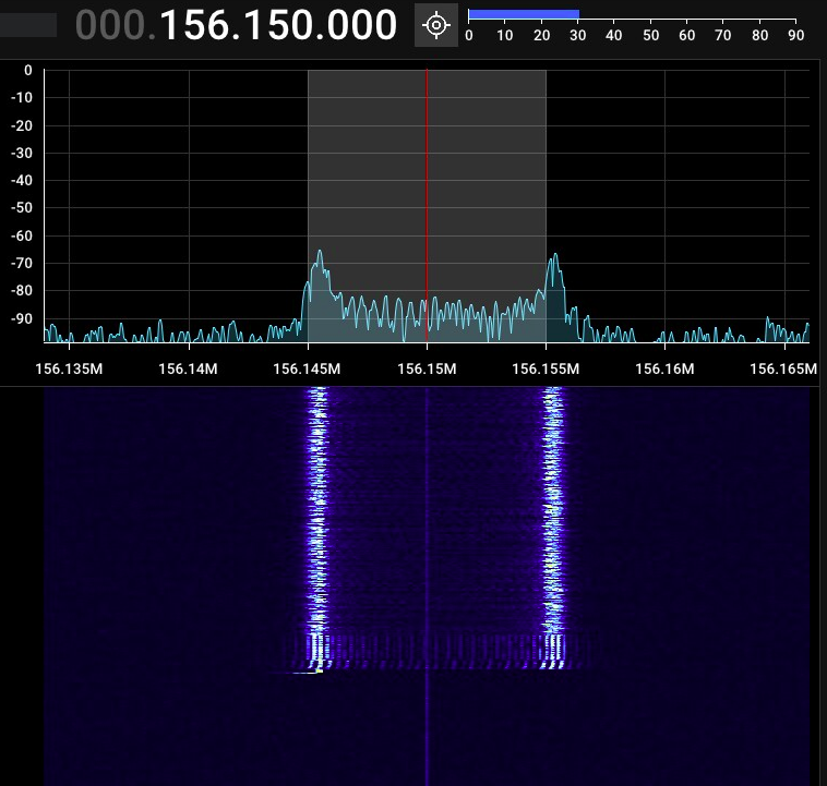
The transmission is likely digital data, where the lower frequency represents 0 and the higher represents 1 (or vice versa). It appears to signal the end of transmission at the lower frequency.
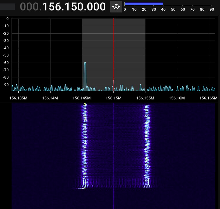
By comparison, 4-FSK has four distinct peaks in the FFT, each representing a digital value (0, 1, 2, or 3).
SEE ALSO
SDR Reference Guide [Link]
Linux Tools for SDR [Link]