OSPF is an open standard (non-proprietary) routing protocol. It is a link-state protocol that allows all routers on the network to map the entire topology and make their own forwarding decisions based on that complete picture.
Given the scenario below, PC1 needs to reach PC2:
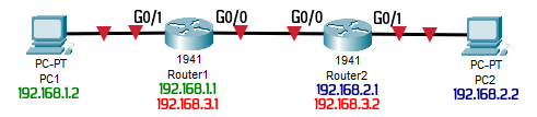
Router1
enable
configure terminal
no ip domain lookup
line con 0
logging synchronous
hostname Router1
interface g0/0
ip address 192.168.3.1 255.255.255.252
no shutdown
interface g0/1
ip address 192.168.1.1 255.255.255.0
no shutdown
Router2
enable
configure terminal
no ip domain lookup
line con 0
logging synchronous
hostname Router2
interface g0/0
ip address 192.168.3.2 255.255.255.252
no shutdown
interface g0/1
ip address 192.168.2.1 255.255.255.0
no shutdown
Example of a Single Area configuration:
Router1
router ospf 1
network 192.168.1.0 0.0.0.255 area 0
network 192.168.3.0 0.0.0.3 area 0
passive-interface GigabitEthernet0/1
Router2
router ospf 1
network 192.168.2.0 0.0.0.255 area 0
network 192.168.3.0 0.0.0.3 area 0
passive-interface GigabitEthernet0/1
For simple networks with few routers this works perfectly. The problem starts when there are many routers, say 50. When one link goes down, all routers begin exchanging link-state messages. This overhead can be reduced by segmenting the network into areas:
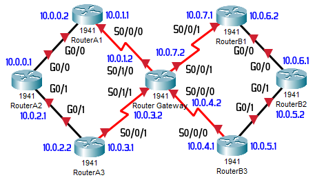
Configuring the interfaces according to the diagram above:
RouterA1
enable
configure terminal
hostname RA1
no ip domain lookup
line con 0
logging synchronous
interface g0/0
ip address 10.0.0.2 255.255.255.0
no shutdown
interface s0/0/0
ip address 10.0.1.1 255.255.255.0
no shutdown
RouterA3
enable
configure terminal
hostname RA3
no ip domain lookup
line con 0
logging synchronous
interface s0/0/1
ip address 10.0.3.1 255.255.255.0
no shutdown
interface g0/1
ip address 10.0.2.2 255.255.255.0
no shutdown
RouterB2
enable
configure terminal
hostname RB2
no ip domain lookup
line con 0
logging synchronous
interface g0/0
ip address 10.0.6.1 255.255.255.0
no shutdown
interface g0/1
ip address 10.0.5.2 255.255.255.0
no shutdown
Router Gateway
enable
configure terminal
hostname Gateway
no ip domain lookup
line con 0
logging synchronous
interface s0/0/0
ip address 10.0.4.2 255.255.255.0
no shutdown
interface s0/0/1
ip address 10.0.7.2 255.255.255.0
no shutdown
interface s0/1/0
ip address 10.0.1.2 255.255.255.0
no shutdown
interface s0/1/1
ip address 10.0.3.2 255.255.255.0
no shutdown
RouterA2
enable
configure terminal
hostname RA2
no ip domain lookup
line con 0
logging synchronous
interface g0/0
ip address 10.0.0.1 255.255.255.0
no shutdown
interface g0/1
ip address 10.0.2.1 255.255.255.0
no shutdown
RouterB1
enable
configure terminal
hostname RB1
no ip domain lookup
line con 0
logging synchronous
interface g0/0
ip address 10.0.6.2 255.255.255.0
no shutdown
interface s0/0/1
ip address 10.0.7.1 255.255.255.0
no shutdown
RouterB3
enable
configure terminal
hostname RB3
no ip domain lookup
line con 0
logging synchronous
interface s0/0/0
ip address 10.0.4.1 255.255.255.0
no shutdown
interface g0/1
ip address 10.0.5.1 255.255.255.0
no shutdown
Configuring OSPF according to the areas in the diagram:
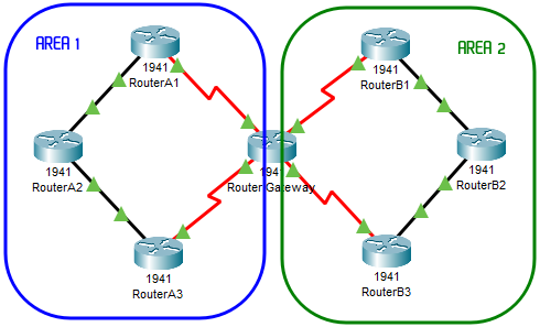
RouterA1
router ospf 1
network 10.0.0.0 0.0.0.255 area 1
network 10.0.1.0 0.0.0.255 area 1
RouterA2
router ospf 1
network 10.0.0.0 0.0.0.255 area 1
network 10.0.2.0 0.0.0.255 area 1
RouterA3
router ospf 1
network 10.0.2.0 0.0.0.255 area 1
network 10.0.3.0 0.0.0.255 area 1
Router Gateway
router ospf 1
network 10.0.1.0 0.0.0.255 area 1
network 10.0.3.0 0.0.0.255 area 1
network 10.0.7.0 0.0.0.255 area 2
network 10.0.4.0 0.0.0.255 area 2
RouterB1
router ospf 1
network 10.0.7.0 0.0.0.255 area 2
network 10.0.6.0 0.0.0.255 area 2
RouterB2
router ospf 1
network 10.0.6.0 0.0.0.255 area 2
network 10.0.5.0 0.0.0.255 area 2
RouterB3
router ospf 1
network 10.0.5.0 0.0.0.255 area 2
network 10.0.4.0 0.0.0.255 area 2
Note:
- Routers A* belong to area 1, so they are called Internal routers;
- Routers B* belong to area 2, so they are called Internal routers;
- Router Gateway has interfaces in both area 1 and area 2, so it is called an Area Border Router;
The router that connects to outside the network requires this configuration:
router ospf 1
default-information originate
ip route 0.0.0.0 0.0.0.0 g0/0
This tells all other routers which one is the ‘gateway of last resort‘ when a destination network is unknown.
To verify the configuration on each router, use the following commands:
show ip route
show ip route ospf
show ip protocols
show ip interface brief
show ip ospf
show ip ospf interface brief
show ip ospf interface
show ip ospf neighbor
show ip ospf database
Reference Bandwidth (for optimized route calculation):
router ospf 1
auto-cost reference-bandwidth 10000
ip ospf cost 22222
Set all interfaces as passive by default:
passive-interface default
no passive-interface Serial0/0/0
no passive-interface Serial0/0/1
To enable authentication for OSPF, apply the following commands on all interfaces on all routers:
ip ospf message-digest-key 1 md5 PASSWORD
ip ospf authentication message-digest
Remember to replace ‘PASSWORD’ with a secret of your choice.
Learn more about [OSPF Single – CertBros]
Learn more about [OSPF Multi – CertBros]
The previous post was about RIPv2 [Read It].
The following post is about EIGRP [Read It].