You got a Celestron 21024 FirstScope Telescope and…
…what are you going to do with it during the day? Hack it!!!
SUMMARY
In this post I will walk through the basic steps and rationale used to develop a motorised mechanism to move both axes electronically.
All source code and 3D files are free to use, share, and modify.
Requirements: a 3D printer, soldering iron, and a DIY mindset.
Out of scope: modifying or damaging the scope in any way (no screw holes or glue).
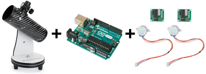
BILL OF MATERIALS
- Mechanism (~$5)
- FDM 3D Printer
- PLA Filament
- Electronics (~$50)
- Arduino UNO Rev3 [Link] – Microcontroller
- Two 28BYJ-48 Stepper Motors
- ULN2003 Driver Module Board
- Small PCB
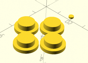
- Four push buttons
- Software ($0)
- Arduino IDE [Link] – Integrated Development Environment
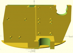
MECHANICAL PARTS
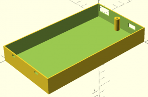
Body
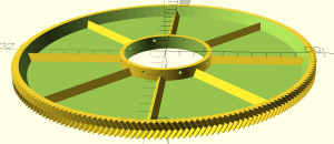
Pan Gear
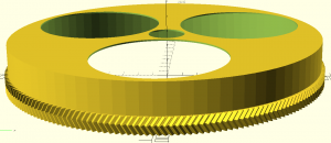
Tilt Gear
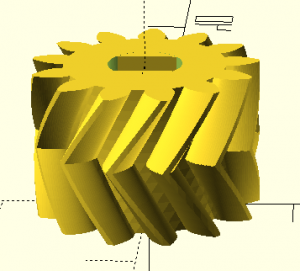
Small Gears (x2)
- STL File [Link]
- SCAD File – Included in the same SCAD files as the large gears.
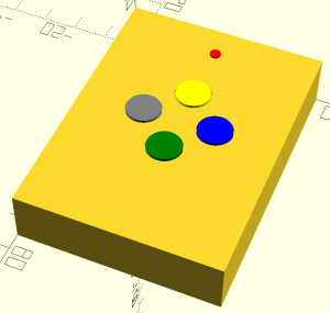
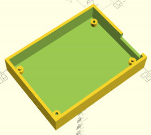
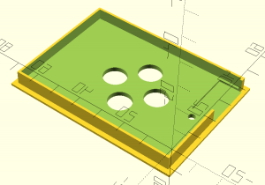
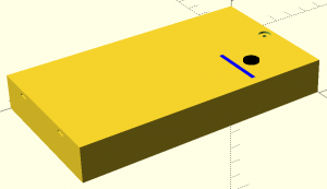
Remote Control
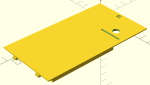
Back Cover
Smartphone Support (optional)
- <pending>
Power Bank (optional)

Assembly
MECHANICAL AND ELECTRONIC ASSEMBLY
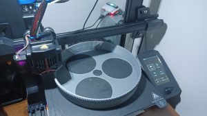
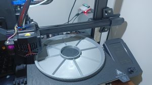
Step #1 – Print the large gears.
The largest dimensions are 208x208mm. Even though my printer supports 220x220mm, two sides did not print correctly when the part was centred on the bed (unsure if this was a printer firmware or slicer issue). Moving it closer to the X and Y origins resolved the problem.
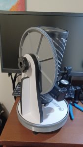
Step #2 – Test the fit of both gears, then remove them.
Both gears attach to the telescope with no screws, bolts, glue, or tape. You may need to sand the inside of the tilt gear for a proper fit, since the telescope counterpart is conical and slightly flexible. If needed, there are 6 small holes in the centre of the gear for pins (not required in my case).
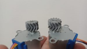
Step #3 – Print two small gears and press them onto the motor shafts.
Note the orientation of the gear before placing it on the stepper motor. It holds by friction alone, so avoid removing it unnecessarily. Both motors take gears aligned in the same direction, making them interchangeable.
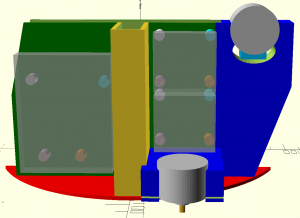
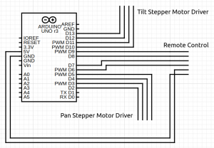
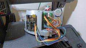
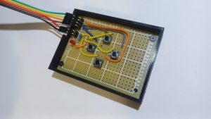
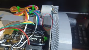
Step #4 – Print and pre-assemble the electronics onto the main body.
The stepper motors require considerable force to seat into the jaws, so it is much easier to make any adjustments before final assembly. The pinout from the Arduino to the drivers and remote control is up to you. Just note the pinout and update the code accordingly.
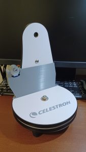
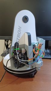
Step #5 – Mount the body onto the neck of the scope.
The body should slide smoothly over the neck with enough friction to hold it firmly in place. The stainless steel screw is an obstacle and needs to be removed.
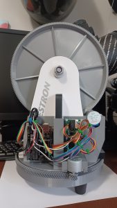
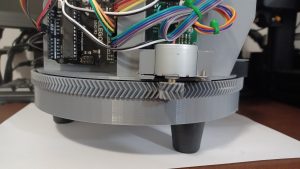
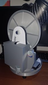
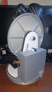
Step #6 – Place the large gears back onto the scope.
Fitting the large gears after the body is much easier. Having the fit already dialled in from Step #2 is important because the herringbone gear type allows no adjustment once engaged. Replacing the original plastic nut with an M10 lock nut also works much better.
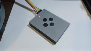
Step #7 – Print and assemble the remote control.
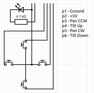
I printed a 0.5mm light guide to make the red LED visible without cutting an open hole. The buttons are held in place only by the assembly order (upside down) and move smoothly with minimal play. Aside from Ground and +5V, the pin sequence does not matter as long as the numbering in the code matches.
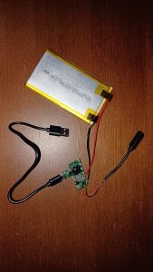
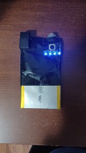
Step #8 – Optionally, print a cover and assemble a power bank.
Any power bank will work. I printed one because I had the parts on hand. I also printed a 0.5mm light guide in white so the LED indicators remain visible while charging and discharging.

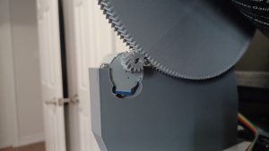
Step #9 – Final gear adjustments.
Rotating the stepper motors on their axis tightens or loosens the pressure between gears. I used a small pin to lock them at the desired tension (very tight). Running a simulation that spins both axes many times in both directions will reveal any issues and wear down rough edges that cause squeaking.


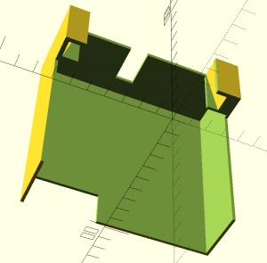
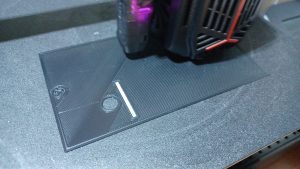
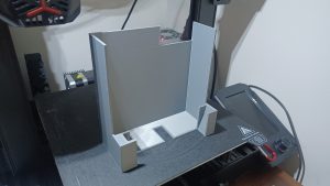
Step #10 – Print and attach the back cover.
The back cover slides down over the wooden neck with no clip or screw, held only by friction. It works well, but here is a tip: glue a neodymium magnet to the body and a small metal piece to the cover for a satisfying, secure fit that takes the build to a higher level of finish.
SOFTWARE
Basic Actuation – Single Speed
//Includes the Arduino Stepper Library
#include

// Steps per Revolution
const int stepsPerRevolution = 2048;
const int nSteps = 1;

// Pins Sequence IN1-IN3-IN2-IN4
Stepper myStepperTilt = Stepper(stepsPerRevolution, 10, 12, 11, 13);
Stepper myStepperPan = Stepper(stepsPerRevolution, 2, 4, 3, 5);

// Button Pins
int pinButtonTiltUp = 9;
int pinButtonTiltDown = 8;
int pinButtonPanCW = 7;
int pinButtonPanCCW = 6;

void setup() {
    // Button Pins Mode
    pinMode(pinButtonTiltUp, INPUT_PULLUP);
    pinMode(pinButtonTiltDown, INPUT_PULLUP);
    pinMode(pinButtonPanCW, INPUT_PULLUP);
    pinMode(pinButtonPanCCW, INPUT_PULLUP);
    myStepperTilt.setSpeed(10);
    myStepperPan.setSpeed(10);
}

void loop() {
  // Button Status
  int statusButtonTiltUp = digitalRead(pinButtonTiltUp);
  int statusButtonTiltDown = digitalRead(pinButtonTiltDown);
  int statusButtonPanCW = digitalRead(pinButtonPanCW);
  int statusButtonPanCCW = digitalRead(pinButtonPanCCW);

  // TILT UP
  if (!statusButtonTiltUp && statusButtonTiltDown && statusButtonPanCW && statusButtonPanCCW) myStepperTilt.step(-nSteps);
  // TILT DOWN
  if (statusButtonTiltUp && !statusButtonTiltDown && statusButtonPanCW && statusButtonPanCCW) myStepperTilt.step(nSteps);
  // PAN CW
  if (statusButtonTiltUp && statusButtonTiltDown && !statusButtonPanCW && statusButtonPanCCW) myStepperPan.step(nSteps);
  // PAN CCW
  if (statusButtonTiltUp && statusButtonTiltDown && statusButtonPanCW && !statusButtonPanCCW) myStepperPan.step(-nSteps);

  // TILT UP + CW
  if (!statusButtonTiltUp && statusButtonTiltDown && !statusButtonPanCW && statusButtonPanCCW) {
    myStepperTilt.step(-nSteps);
    myStepperPan.step(nSteps);
  }
  // TILT DOWN + CW
  if (statusButtonTiltUp && !statusButtonTiltDown && !statusButtonPanCW && statusButtonPanCCW) {
    myStepperTilt.step(nSteps);
    myStepperPan.step(nSteps);
  }
  // PAN UP + CCW
  if (!statusButtonTiltUp && statusButtonTiltDown && statusButtonPanCW && !statusButtonPanCCW) {
    myStepperTilt.step(-nSteps);
    myStepperPan.step(-nSteps);
  }
  // PAN DOWN + CCW
  if (statusButtonTiltUp && !statusButtonTiltDown && statusButtonPanCW && !statusButtonPanCCW) {
    myStepperTilt.step(nSteps);
    myStepperPan.step(-nSteps);
  }
}
Advanced Actuation – Accelerated Speed
//Includes the Arduino Stepper Library
#include

// Steps per Revolution
const int stepsPerRevolution = 2048;
const int nSteps = 1;

// Pins Sequence IN1-IN3-IN2-IN4
Stepper myStepperTilt = Stepper(stepsPerRevolution, 10, 12, 11, 13);
Stepper myStepperPan = Stepper(stepsPerRevolution, 2, 4, 3, 5);

// Button Pins
int pinButtonTiltUp = 9;
int pinButtonTiltDown = 8;
int pinButtonPanCW = 7;
int pinButtonPanCCW = 6;
int speed = 1;
float speedAccellerated = 1.0;
float speedAccelleration = 0.02;

void setup() {
    // Button Pins Mode
    pinMode(pinButtonTiltUp, INPUT_PULLUP);
    pinMode(pinButtonTiltDown, INPUT_PULLUP);
    pinMode(pinButtonPanCW, INPUT_PULLUP);
    pinMode(pinButtonPanCCW, INPUT_PULLUP);
}

void loop() {
  // Button Status
  int statusButtonTiltUp = digitalRead(pinButtonTiltUp);
  int statusButtonTiltDown = digitalRead(pinButtonTiltDown);
  int statusButtonPanCW = digitalRead(pinButtonPanCW);
  int statusButtonPanCCW = digitalRead(pinButtonPanCCW);

  // TILT UP
  if (!statusButtonTiltUp && statusButtonTiltDown && statusButtonPanCW && statusButtonPanCCW) {
    myStepperTilt.step(-nSteps);
    speedAccellerated = speedAccellerated + speedAccelleration;
  }
  // TILT DOWN
  else if (statusButtonTiltUp && !statusButtonTiltDown && statusButtonPanCW && statusButtonPanCCW) {
    myStepperTilt.step(nSteps);
    speedAccellerated = speedAccellerated + speedAccelleration;
  }
  // PAN CW
  else if (statusButtonTiltUp && statusButtonTiltDown && !statusButtonPanCW && statusButtonPanCCW) {
    myStepperPan.step(nSteps);
    speedAccellerated = speedAccellerated + speedAccelleration;
  }
  // PAN CCW
  else if (statusButtonTiltUp && statusButtonTiltDown && statusButtonPanCW && !statusButtonPanCCW) {
    myStepperPan.step(-nSteps);
    speedAccellerated = speedAccellerated + speedAccelleration;
  }
  // TILT UP + CW
  else if (!statusButtonTiltUp && statusButtonTiltDown && !statusButtonPanCW && statusButtonPanCCW) {
    myStepperTilt.step(-nSteps);
    myStepperPan.step(nSteps);
    speedAccellerated = speedAccellerated + speedAccelleration;
  }
  // TILT DOWN + CW
  else if (statusButtonTiltUp && !statusButtonTiltDown && !statusButtonPanCW && statusButtonPanCCW) {
    myStepperTilt.step(nSteps);
    myStepperPan.step(nSteps);
    speedAccellerated = speedAccellerated + speedAccelleration;
  }
  // PAN UP + CCW
  else if (!statusButtonTiltUp && statusButtonTiltDown && statusButtonPanCW && !statusButtonPanCCW) {
    myStepperTilt.step(-nSteps);
    myStepperPan.step(-nSteps);
    speedAccellerated = speedAccellerated + speedAccelleration;
  }
  // PAN DOWN + CCW
  else if (statusButtonTiltUp && !statusButtonTiltDown && statusButtonPanCW && !statusButtonPanCCW) {
    myStepperTilt.step(nSteps);
    myStepperPan.step(-nSteps);
    speedAccellerated = speedAccellerated + speedAccelleration;
  }
  else {
    speedAccellerated = 1;
  }

  if (speedAccellerated <= 10) speed = speedAccellerated;
  myStepperTilt.setSpeed(speed);
  myStepperPan.setSpeed(speed);
}
DEMO
LINKS
Thingiverse [Link]
GitHub [Link]