Using the same scenario from the VLAN and TRUNK post [Read It], where both switches had the VLANs configured manually, we will now create a Server-Client hierarchy to centralize the VLAN configuration and make the network easier to manage.
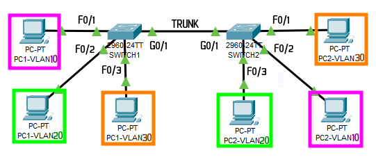
Switch1
enable
configure terminal
hostname Switch1
no ip domain lookup
line con 0
logging synchronous

interface f0/1
switchport mode access
switchport access vlan 10
interface f0/2
switchport mode access
switchport access vlan 20
interface f0/3
switchport mode access
switchport access vlan 30

interface range f0/4-24
shutdown

interface g0/1
switchport mode trunk
Switch2
enable
configure terminal
hostname Switch2
no ip domain lookup
line con 0
logging synchronous

interface f0/1
switchport mode access
switchport access vlan 30
interface f0/2
switchport mode access
switchport access vlan 10
interface f0/3
switchport mode access
switchport access vlan 20

interface range f0/4-24
shutdown

interface g0/1
switchport mode trunk
After setting up the trunks, configure VTP in client-server mode:
Switch1
vtp domain DFT
vtp mode server
vtp password dft
vtp pruning

vlan 10
name Pink
vlan 20
name Green
vlan 30
name Orange
Switch2
vtp domain DFT
vtp mode client
vtp password dft
Note: No additional configuration is needed on the client side. The VTP protocol will automatically propagate all VLAN information to the client.
To verify the configuration on each switch, use the following commands:
show vlan brief
show vtp status
Learn more about [VTP – CertBros]